Maverick and Comet Repair
Emission Controls
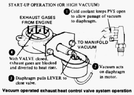
Vacuum Operated Heat Control Valve
(VOHV)
To further aid cold start drivability during
engine warmup, 1975-77 V8 engines use a VOHV located between the
exhaust manifold and the exhaust inlet (header) pipe.
When the engine is first started, the valve is closed, blocking exhaust gases from exiting from one bank of cylinders. These gases are then diverted back through the intake manifold crossover passage under the carburetor. The result is quick heat to the carburetor and choke.
The VOHV is controlled by a ported vacuum switch which uses manifold vacuum to keep the vacuum motor on the valve closed until the coolant reaches a predetermined "warm-up" valve. When the engine is warmed-up, the PVS shuts off vacuum to the VOHV, and a strong return spring opens the VOHV butterfly.
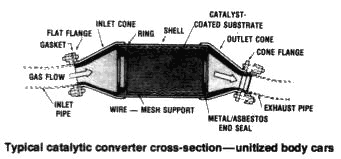
Catalytic Converter
System
Beginning in 1975, catalytic converters are used
to clean up carbon monoxide and hydrocarbon emissions after they
leave the engine. The use of a single converter, located in the
exhaust system between the engine and muffler, allows the engine to
be tuned with more ignition advance, permitting better drivability,
gas mileage, and performance. In 1975, Ford planned to use the
converters only on California models using the 250 Six and 302 V8,
and on the 49 states version of the 200 Six. However, a mid-year
economy and drivability program saw the installation of the
converters on all 1975 models nationwide. So, your 1975 49 states
250 Six or 302 V8 model may or may not have a converter. The engine
emission equipment decal, located on the valve cover of the engine,
will give you a definitive answer. All 1976 and 1977 models have the
converter.
The catalyst agent inside each converter consists of platinum or palladium crystallites spread over a ceramic honeycomb substrate. The surface area exposed to the exhaust gases is roughly equivalent to that of a football field. Unlike the Thermactor system, no actual combustion takes place inside the converter. Instead, the catalyst triggers a rapid oxidation (chemical change), of the pollutants into water vapor and sulphur dioxide. The sulphur dioxide is the occasional "rotten egg" smell that you will notice on a humid day, or if the car is running overly rich.
If the car is kept in proper tune, and if only lead-free fuel is used, the converter is designed to last a minimum of 50,000 miles before needing replacement.
Component Service
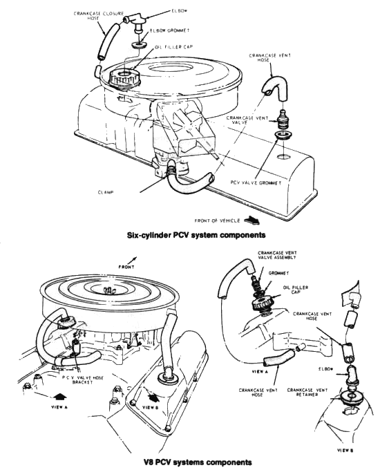
POSITIVE CRANKCASE VENTILATION SYSTEM
- Remove the PCV system components, filler cap, PCV valve, hoses, tubes, fittings, etc. from the engine.
- Soak the rubber ventilation hose(s) in a low volatility petroleum base solvent.
- Clean the rubber ventilation hose(s) by passing a suitable cleaning brush through them.
- Thoroughly wash the rubber hoses in a low volatility petroleum base solvent and dry with compressed air.
- Thoroughly
wash the crankcase breather cap, if so equipped, in a low volatility
petroleum base solvent and shake dry. Do
not dry with compressed air; damage to the filtering media may result. - Thoroughly clean tubes, fittings, connections to assure unobstructed flow of emission gases.
- Install new PCV valve and re-install previously removed hoses, tubes, fittings, etc. to their proper location.
- Replace any system component that shows signs of damage, wear or deterioration as required.
- Replace any hose or tube that cannot be cleaned satisfactorily.
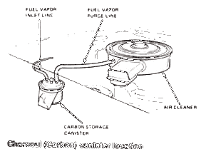
FUEL EVAPORATIVE CONTROL SYSTEM
Except for 1970 Mavericks manufactured
for sale in California, the only service performed on the
evaporative control system is the replacement of the charcoal
(carbon) canister at the intervals listed in the maintenance
schedule in Chapter 1. The above mentioned California registered
1970 Mavericks require replacement of the 3-way vent valve once a
year or every 12,000 miles. The procedure is as follows.
- Working under the vehicle, disconnect two hoses from the control valve.
- Remove two attaching bolts and remove the valve from the frame members.
- To install, position the valve to the frame member and install two attaching bolts.
- Connect the two hoses to the valve assembly.
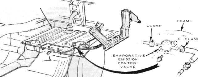
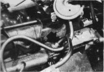
Evaporative control 3-way vent valve location (1970
California models only)
EXHAUST GAS
RECIRCULATION SYSTEM
NOTE: 1975—77 models using
unleaded fuel do not require regular EGR system cleaning.
EGR Valve Cleaning
Remove the EGR valve for cleaning. Do not strike or pry on the valve
diaphragm housing or supports, as this may damage the valve
operating mechanism and/or change the valve calibration. Check
orifice hole in the EGR valve body for deposits. A small hand drill
of no more than 0.060 in. diameter may be used to clean the hole if
plugged. Extreme care must be taken to avoid enlarging the hole or
damaging the surface of the orifice plate.
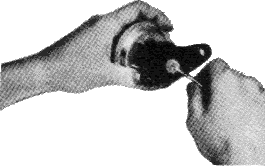
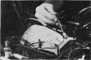
Cleaning EGR Valve Orifice
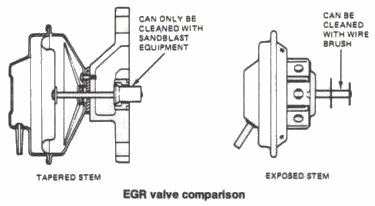
VALVES WHICH CANNOT BE DISASSEMBLED
Valves which are riveted or otherwise permanently assembled should
be replaced if highly contaminated; they cannot be cleaned.
VALVES WHICH CAN BE DISASSEMBLED
Separate the diaphragm section from the main mounting body. Clean
the valve plates, stem, and the mounting plate, using a small power
driven rotary type wire brush. Take care not to damage the parts.
Remove deposits between stem and valve disc by using a steel blade
or shim approximately 0.028 inch thick in a sawing motion around the
stem shoulder at both sides of the disc.
The poppet must wobble and move axially before re-assembly.
Clean the cavity and passages in the main body of the valve with a power driven rotary wire brush. If the orifice plate has a hole less than 0.450 inch, it must be removed for cleaning. Remove all loosened debris using shop compressed air. Reassemble the diaphragm section on the main body using a new gasket between them. Torque the attaching screws to specification. Clean the orifice plate and the counter bore in the valve body. Re-install the orifice plate using a small amount of contact cement to retain the plate in place during assembly of the valve to the carburetor spacer. Apply cement only to outer edges of the orifice plate to avoid restriction of the orifice.
EGR Supply Passages
and Carburetor Spacer Cleaning
Remove the carburetor and
carburetor spacer on engines so equipped. Clean the supply tube with
a small power driven rotary type wire brush or blast cleaning
equipment. Clean the exhaust gas passages in the spacer using a
suitable wire brush and/or scraper. The machined holes in the spacer
can be cleaned by using a suitable round wire brush. Hard encrusted
material should be probed loose first, then brushed out. On
six-cylinder engines, the external tube from the exhaust manifold
must be removed and cleaned with a brush.
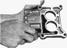
Cleaning EGR carburetor spacer exhaust passages
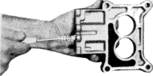
Cleaning EGR carburetor spacer machined holes
EGR Exhaust Gas Channel Cleaning
Clean the exhaust gas channel, where applicable, in the intake
manifold, using a suitable carbon scraper. Clean the exhaust gas
entry port in the intake manifold by hand passing a suitable drill
bit through the holes to auger out the deposits. Do not use a wire
brush. The manifold riser bore(s) should be suitably plugged during
the above action to prevent any of the residue from entering the
induction system.
External Exhaust Gas Supply Tube—Six-Cylinder Engine
Cleaning EGR exhaust gas entry port in intake manifold