Maverick and Comet Repair
Engine Electrical
ENGINE ELECTRICAL
Charging System
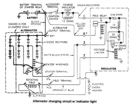
The charging system is composed of the alternator, alternator
regulator, charging system warning light, batten., and fuse link
wire.
A failure of any component of the charging system can cause
the entire system to stop functioning. Because of this, the charging
system can be very difficult to troubleshoot when problems occur.
When the ignition key is turned on, current flows from the batters', through the charging system indicator light on the instrument panel, to the voltage regulator, and to the alternator. Since the alternator is not producing any current, the alternator warning light comes on. When the engine is started, the alternator begins to produce current and turns the alternator light off. As the alternator turns and produces current, that current is divided in two ways: part to the battery to charge the battery and power the electrical components of the vehicle, and part is returned to the alternator to enable it to increase its output. In this situation, the alternator is receiving current from the battery and from itself. A voltage regulator is wired into the current supply to the alternator to prevent it from receiving too much current which would cause it to put out too much current. Conversely, if the voltage regulator does not allow the alternator to receive enough current, the battery will not be fully charged and will eventually go dead.
The battery is connected to the alternator at all times, whether the ignition key is turned on or not. If the battery were shorted to ground, the alternator would also be shorted. This would damage the alternator. To prevent this, a fuse link is installed in the wiring between the battery and the alternator on all 1970 and later models. If the battery is shorted, the fuse link is melted, protecting the alternator.
Since the alternator, the alternator regulator, the charging system warning light, the battery and the fuse link are all interconnected, the failure of one component can cause the others to become inoperative.
ALTERNATOR PRECAUTIONS
Several precautions must be observed with
alternator equipped vehicles to avoid damaging the unit. They are as
follows:
- If the battery is removed for any reason, make sure that it is reconnected with the correct polarity. Reversing the battery connections may result in damage to the one way rectifiers.
- When utilizing a booster battery as a starting aid, always connect it as follows: positive to positive, and negative (booster battery to a good ground on the engine of the car being started.
- Never use a fast charger as a booster to start cars with alternating-current (AC) circuits.
- When servicing the battery with a fast charger, always disconnect the car battery cables.
- Never attempt to polarize an alternator.
- Avoid long soldering times when replacing diodes or transistors. Prolonged heat is damaging to alternators.
- Do not use test lamps of more than 12 volts (V) for checking diode continuity.
- Do not short across or ground any of the terminals on the alternator.
- The polarity of the battery, alternator, and regulator must be matched and considered before making any electrical connections within the system.
- Never separate the alternator on an open circuit. Make sure that all connections within the circuit are clean and tight.
- Disconnect the battery terminals when performing any service on the electrical system. This will eliminate the possibility of accidental reversal of polarity.
- Disconnect the battery ground cable if arc welding is to be done on any part of the car.
ALTERNATOR
While internal alternator repairs are possible, they require
specialized tools and training. Therefore, it is advisable to
replace a defective alternator, or have it repaired by a qualified
shop.
Removal and Installation
- Disconnect the negative battery cable from the battery.
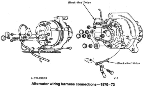
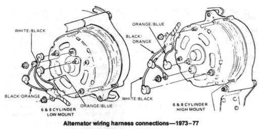
- Disconnect the wires from the rear of the alternator.
- Loosen the alternator mounting bolts and remove the belt.
- Remove the alternator mounting bolts and remove the alternator.
- To install, position the alternator on the engine and install the attaching bolts.
- Connect the wires on the rear of the alternator.
- Position the belt on the alternator.
- Adjust alternator belt tension as described below under "Belt Tension Adjustment."
- Connect the negative battery cable.
FUSE LINK
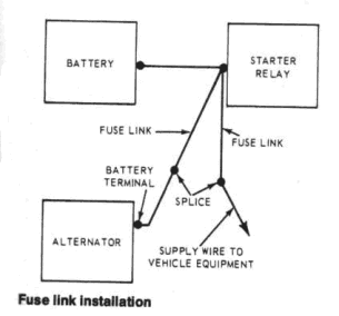
The fuse link is a short length of insulated-wire contained in the
alternator wiring harness, between the alternator and the starter
relay. The fuse link is several wire gauge sizes smaller than the
other wires in the harness. If a booster battery is connected
incorrectly to the car battery or if some component of the charging
system is shorted to ground, the fuse link melts and protects the
alternator. The fuse link is attached to the starter relay. The
insulation on the wire reads: Fuse Link. A melted fuse link can
usually be identified by cracked or bubbled insulation. If it is
difficult to determine if the fuse link is melted, connect a test
light to both ends of the wire. If the fuse link is not melted, the
test light will light showing that an open circuit does not exist in
the wire.
Fuse Link Replacement
Fuse links originally installed in your car are black on 1970-71
models and the color of the circuit being protected on 1972 and
later models. Service replacements are green or black, depending on
usage. Black service replacements are used with cars using 38 and 42
amp alternators, and green service replacements on cars using 55 or
61 amp alternators. All 1972 and later models use color coded flags
molded on the wire or on the terminal insulator to identify the wire
gauge of the link. Color identification is as follows: Red-18 gauge
wire, orange-16 gauge wire, green-14 gauge wire.
- Disconnect the negative battery cable.
- Disconnect the eyelet of the fuse link from the starter relay.
- Cut the other end of the fuse link from the wiring harness at the splice.
- Connect the eyelet
end of a new fuse link to the starter relay.
NOTE: Use only an original equipment type fuse link. Under no conditions should standard wire be substituted. - Splice the open end of the new fuse link into the wiring harness.
- Solder the splice with rosin-core solder and wrap the splice with electrical tape. This splice must be soldered.
- Connect the negative battery cable.
- Start the engine, to check to see that the new connections complete the circuit.
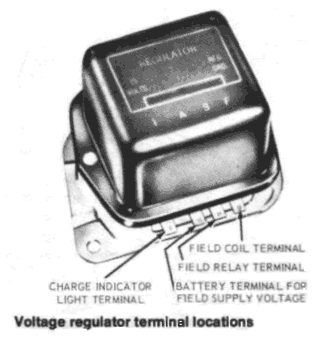
VOLTAGE REGULATOR
The voltage regulator is an electromechanical device which controls
the output of the alternator. If the regulator did not limit the
voltage output of the alternator, the excessive output could burn
out the components of the electrical system. In addition, the
regulator compensates for seasonal temperature changes as they
affect voltage output.
The voltage regulator is preset at the factory and is not adjustable.
Removal And Installation
- Remove the battery ground cable. On models with the regulator mounted behind the battery, it is necessary to remove the battery hold-down, and to move the battery.
- Remove the regulator mounting screws.
- Disconnect the regulator from the wiring harness.
- Connect the new regulator to the wiring harness.
- Mount the regulator to the regulator mounting plate. The radio suppression condenser mounts under one mounting screw; the ground lead under the other mounting screw. Tighten the mounting screws.
- If the battery was moved to gain access to the regulator, position the battery and install the hold-down. Connect the batten,' ground cable, and test the system for proper voltage regulation.